BIWIN M560 1TB | Test Report
Test Platform
| Item | Test configuration |
|---|---|
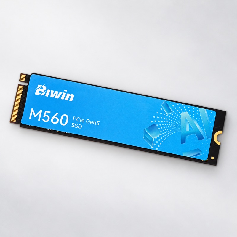
| Drive | BIWIN M560 1TB; M.2 2280, PCIe Gen5 ×4, NVMe 2.0, DRAM-less |
| Sample | One sample; serial number BSBK46150201505 |
| Firmware | BS3563VN |
| Platform | NUC, Core Ultra 9 285H, 16 GB RAM; Ubuntu 26.04.1, Linux 7.0.0-38 |
| Tools | PyNVMe3 26.11; Quarch PPM for power measurement |
| PCIe Link | 32 GT/s ×4 |
| HMB | 64 MB |
Test Procedure
PyNVMe3 was used for TP1 protocol tests and TP2 benchmarks covering performance, stress, power-on time and related behavior. Power was measured with a Quarch PPM throughout.
| Category | Test ID | Scope |
|---|---|---|
| Protocol and reset | TP1 | Core I/O, HMB, registers, TCG and controller reset functions. |
| Low-power states | TP2.a | Power consumption and I/O response in low-power states. |
| Performance and power | TP2.b | Sequential, random and mixed I/O performance, latency and supply power at different write-workflow checkpoints. |
| Stress and data verification | TP2.c | Sustained stress followed by readback verification of known data across the drive. |
| Sudden power loss and recovery | TP2.d | Sudden power loss during random I/O, recovery timing and data verification. |
| Normal power cycles | TP2.e | Normal shutdown and power cycles, with recovery-to-access timing. |
| Advertised performance | TP2.f | Peak sequential and random read/write performance in a small region. |
| Link speed switching | TP2.g | Dynamic Gen2–Gen5 link-speed changes under a read workload. |
| Model loading | TP2.h | Read synthetic model images of different sizes at various worker counts and queue depths. |
Product Radar
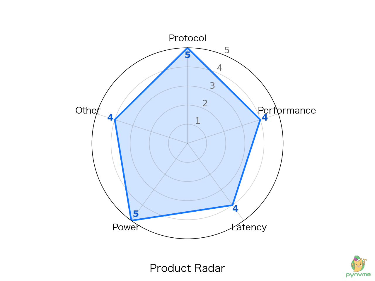
This chart shows five aspects of the tested sample. Protocol covers functions related to NVMe and PCIe specifications; performance covers read and write capability; latency concerns response time; power covers electricity consumption; and other includes stress, power cycling and recovery. Each dimension is scored from 1 to 5, with a higher score farther from the center.
Performance Positioning
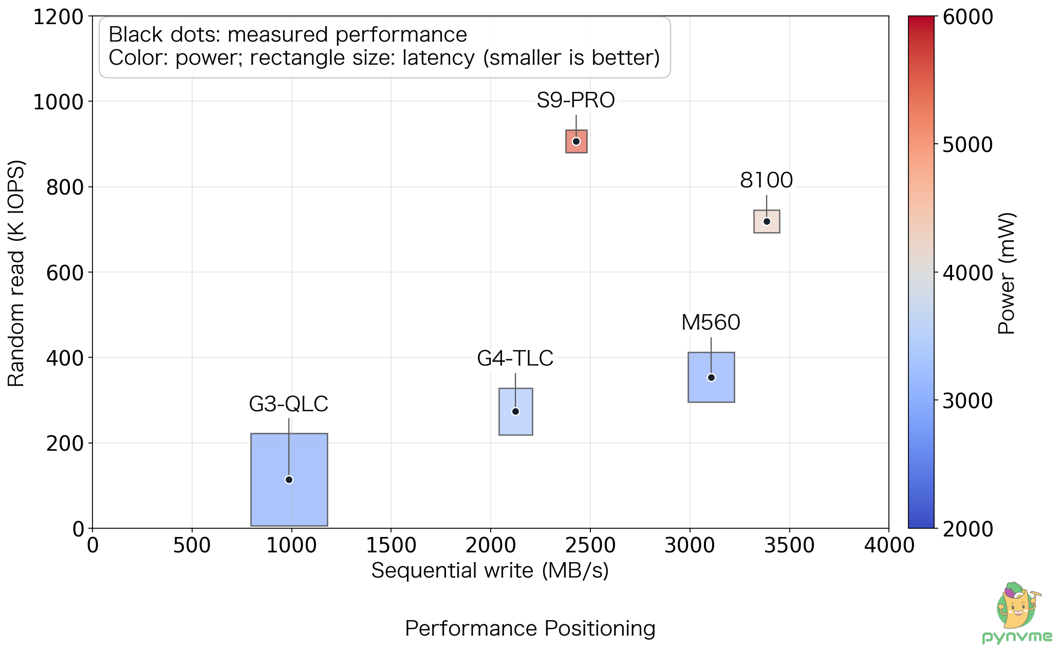
Each black dot places one drive according to two tests. Farther right means higher sequential write speed, such as when saving a large file; higher up means stronger random read performance, such as when reading data from different locations.
The rectangle around each dot represents longer response times in two workloads. Its width corresponds to mixed reads and writes during sequential writing; its height corresponds to random-write latency at the 90% workflow checkpoint. Smaller dimensions indicate shorter measured tail latency in the respective tests. Color represents power consumption during testing: blue is lower and red is higher.
Model Loading Time
This test simulates reading model images from an SSD and compares loading times at different queue counts and queue depths.
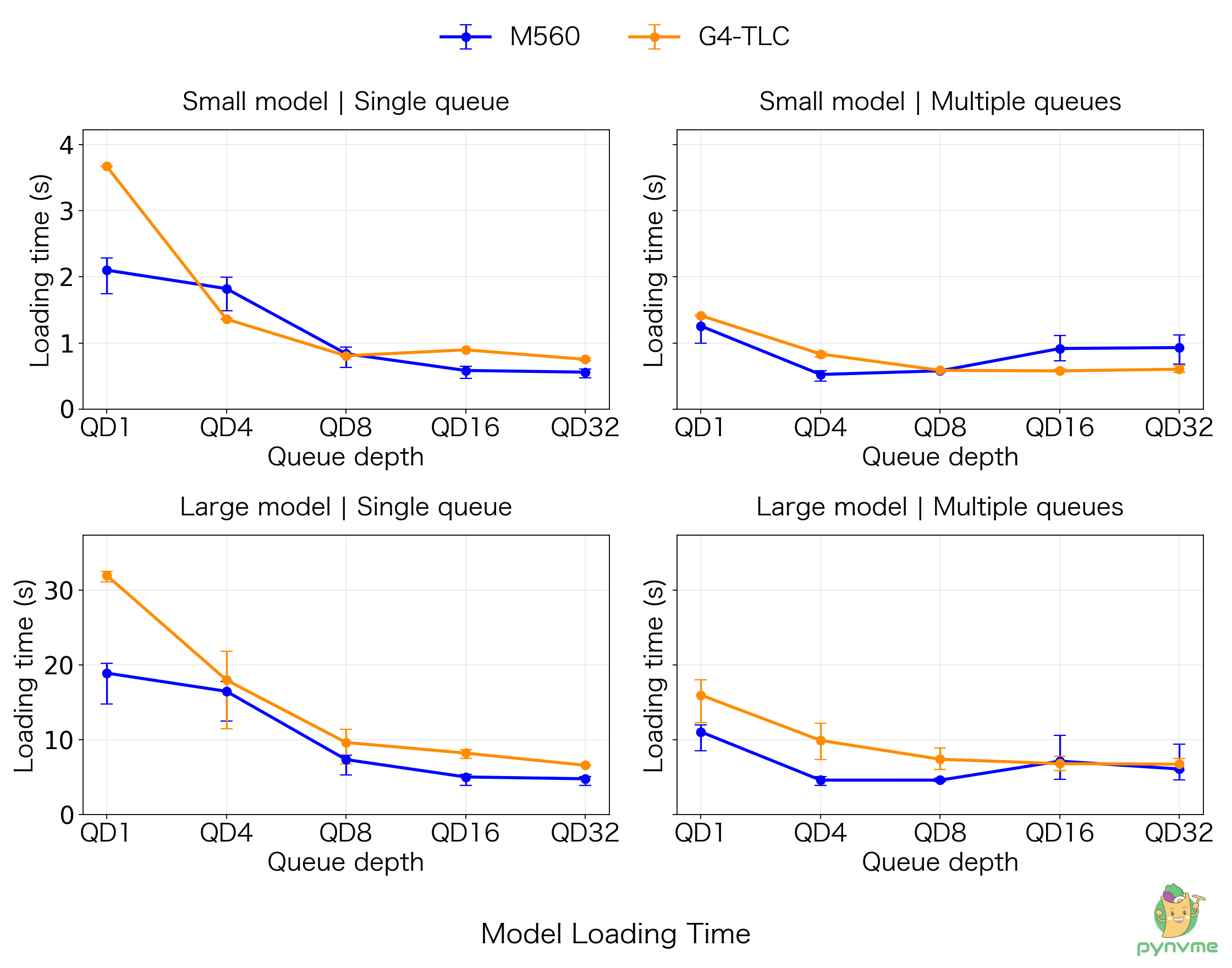
The four panels show small (4.7 GiB) and large (40 GiB) model images, each with a single queue and multiple queues. Queue depth on the horizontal axis is the number of read requests that each queue can issue at the same time; the vertical axis shows average read time. A lower line means the read completed sooner under those test conditions. Each point summarizes multiple measurements; the vertical bars show the observed range.
Key Issues
| ID | Test ID | Description |
|---|---|---|
| M560-01 | TP2.b | Full-drive high-queue-depth random-write performance was low at all five workflow checkpoints and substantially below the tested G3 QLC sample. |
| M560-02 | TP2.d | The first read after each of 100 sudden-power-loss recovery cycles took approximately 7 seconds. |
| M560-03 | TP2.h | Loading time increased at higher queue depths with multiple queues. |